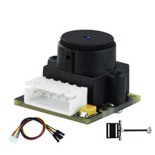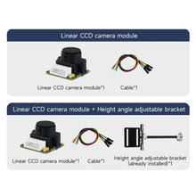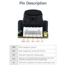
1. Working voltage: DC 3.3V-5V
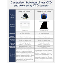
2. Output signal: 128x1 pixels
3. Response time: 100ms (test routine)
4. Equipped with lens: 56-degree distortion-free lens
5. Detection distance: within 5-40cm (because of the lens, it is not suitable for long-distance forward-looking tests)
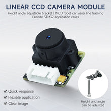
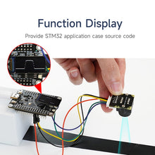
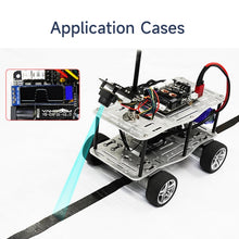
6. Application occasions: STM32 single-chip CCD camera black line tracking, obstacle avoidance, multi-channel line inspection and other image processing electronic design
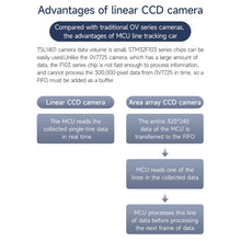
7. The linear CCD module can collect the image information of the ground line, and extract the characteristic information of the line through the image processing algorithm, so as to achieve higher precision line inspection
8. Stronger adaptability: linear CCD module line inspection is not limited by lighting conditions, and can be used under various lighting conditions
9. Stronger scalability: Linear CCD module line inspection can adapt to different line inspection scenarios by changing image processing algorithms and parameters to achieve wider applications
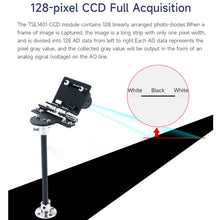
10. The linear CCD module contains 128 linearly arranged photodiodes. When a frame of image is taken, the image is a long strip with only one pixel width, and is divided into 128 AD data from left to right, and each AD data represents a pixel. Gray value, the collected gray value will be output in the form of analog signal (voltage) on the AO line
11. Using 128-pixel linear array CCD, working voltage 3.3-5V, detection distance 5-40 cm
12. Onboard 5PIn-XH2.54 anti-reverse connection interface, the pin distribution is GND, VCC, AO, CLK, SI
13. Smart car tracking for higher speeds
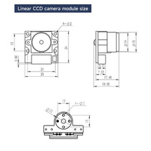
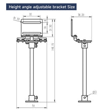
14. Dimensions: 28x26x40 mm
15. Weight: 7.2 grams (module)
Working principle:
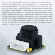
When shooting a scene, the light reflected by the scene is transmitted to the CCD through the lens of the camera. When the CCD is exposed, the photodiode is excited by the light to release the charge, and the current generated by the photodiode is controlled by the control signal circuit in the photosensitive element. The output of the transmission circuit, the CCD will collect the electrical signals generated by one imaging, and output them to the amplifier in a unified manner. The amplified and filtered electrical signals are sent to the A/D, and the A/D converts the analog electrical signals into digital signals. The size of the signal is directly proportional to the strength of the electrical signal, that is, the level of the voltage. These values are actually the data of the image. By processing the returned data, it can be used for smart car path recognition, tracking, and obstacle avoidance
Specification:
| Package Weight |
|


